
Double gripper design – learn the basic steps how to make great mechanical design. Read high value tips about mechanical design. Be few steps in front of most of the mechanical design engineers worldwide. So let`s start…

Pick and place – Double gripper and a single rod actuator
Automation design – master the pick and place technology.
Starting the design of the double gripper – sketches and ideas.

Basic sketch
At the beginning the project starts with asignment. For this specific case there are going to be two pneumatic grippers. They will be moved my a single rod double acting pneumatic cylinder. Also there are guiders needed for the back and forward movement.
For our case we don`t need to calculate gripping forces and speeds, because to do so there is particular load for mooving. The pneumatic components can be picked from lots of suppliers worldwide. In their catalogs there are mounting dimensions, forces, prices and more data.
One thing to be aware is tipically most of the single rod double acting cylinders have different forces for both directions due to the rod geometry.

Grippers type
When choosing the pneumatic grippers we are selecting two fingers type.
It is important to select the right opening capacity D. Also if the system is going to moove fast or has high accelarating and stopping speeds it is better to check the gripping force.
Guiding system
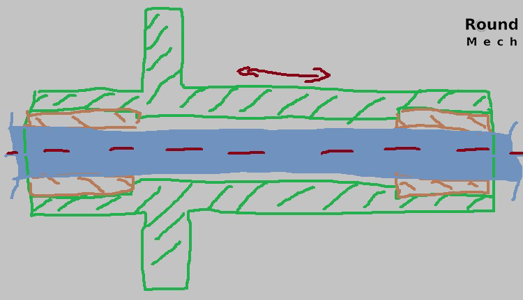
For the back and forward movement the pneumatic cylinder needs to be supported in order to be able to carry the load.
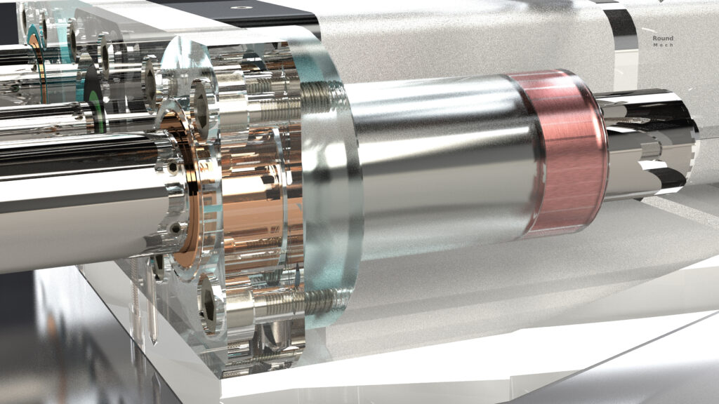
So we sketched a holder for two bushings. There are lots of possible solutions, for example with ball bearing bushes or other. In this case, simple bronze bushings can do the job.
3D models of the Double gripper – details and assemblies


More parts added to the assemblie
Using one of the CAD softwares we created the 3D models and assemblies. There are more components added to the initial idea – we added two magnet sensors at the top of each of the two grippers. Also we added optic sensor to detect the products positions.


1 – Magnet sensors for detecting open/closed positions;
2 – Hardened fingers;
3 – Plugs;
4 – Optical sensor.
The magnet sensors (1) have mini screw to fix the position.
We also designed gripping fingers (2). We decided to make them lighter by designing milling holes. The reason we need them lighter is that we can use smaller and cheeper cylinders for fripping and moving. Also the air consumption is less and the forces are smaller, so the system can moove faster.
Plugs (3) are needed for connecting the pneumatics with the air compressor, using the air pipes.
The optical sensor (4) is hidden in the upper plate. It allowes the device to detect items in front of it.

Sensors:
1. Stopper screw;
2. Green light of the sensor;
3. Optic sensor working surface;
4. Jaws gripping surfaces.
When the gripper opens it activates one of the sensors and the green light (2) starts. Stopper screw (1) fix the sensor position. The other sensor activates when the gripper is closed with the product between the jaws` gripping surfaces (4). The lifgt sensor is just fixed with the working surface carefully covered inside the plate.
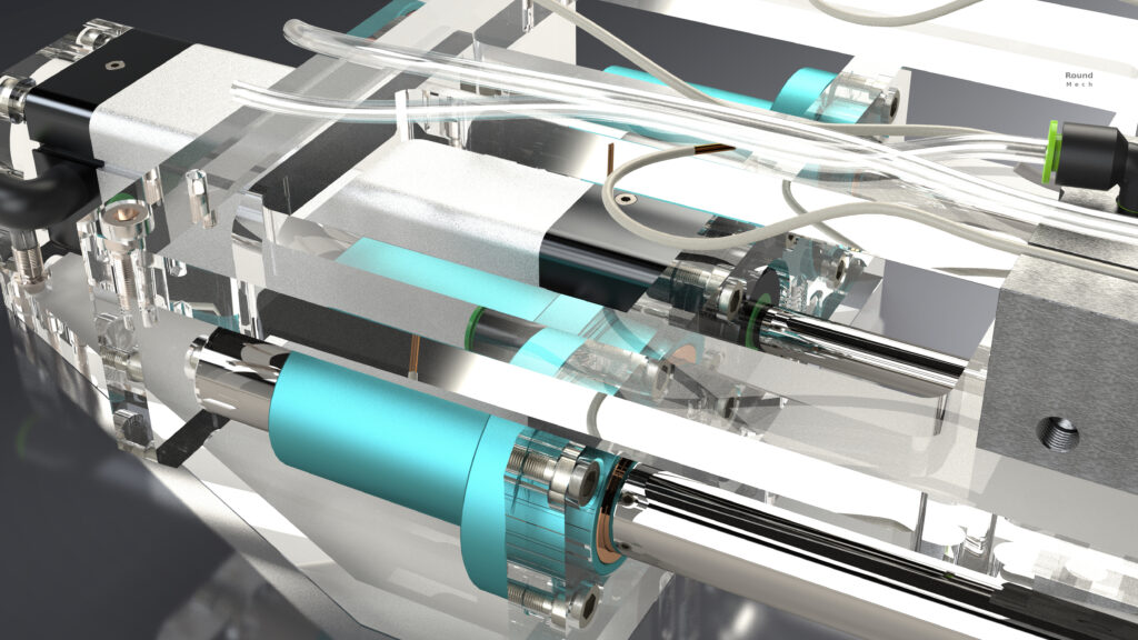
Here are some images with the plates made transparent so the bushings, screws and pins are visible.


Bearing bodies and bushings inside – 3D models and drawings


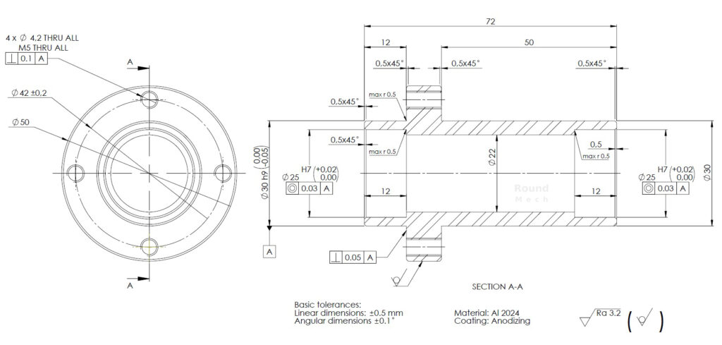

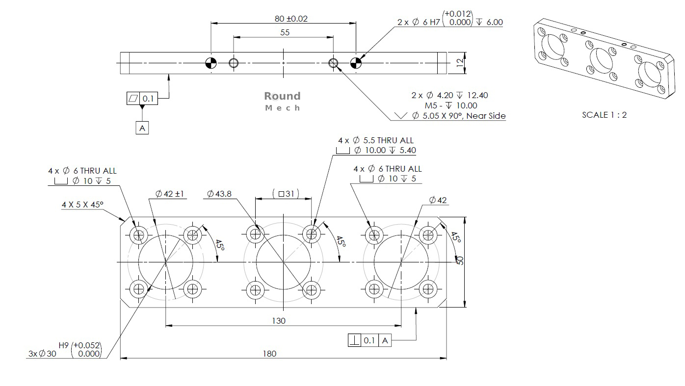
Proper dimensioning and choosing the correct tolerances.
The correct tolerances are very important for the smooth linear movement and assembling ability of the mechanism.
The upper drawing is for the bearings (bushings) body and the second is for the bushings themselves.
The hole for fitting the bushings is made with H7 tolerance, the outer diameter of the bushings is r7. This is press fit and will make sure they won`t dissasemble durings work.
The inner diameter of the bushings is with double plus tolerance. This way we can pick guiders with h9 workpiece tolerance for example.
This page is about to be updated with more detailed information. There will be some drawings and more explanations about the details, how they work and why we chose them particularly. So check our Design Page regularly and make sure you won`t miss it.
Also you can visit our Instagram where we usually post more images varians and will noitify our followers for eventual update of the page.